This is a general view of the headstock end of the lathe taken shortly after its aquisition and with only a limited amount of cleaning and oiling.
This is a 3 1/2 inch centre height lathe. Its date of manufacture is not known but the fact that it has Vee pulley drive rather than flat belt puts it around the late thirties. All the fixings are Whitworth, with a mixture of large and small headed nuts which suggests it might have been made during WW2 possibly with Birmel being licenced by Mellor.
The design is essentially the same as the Mellor type A but with minor changes. The main mandrel has a 3MT internal taper and the tailstock is 2MT. Also, there is a different method of engaging the carriage and cross slide power feeds using knurled knobs into which a 3/16 inch rod can be inserted to increase purchase.
This is a general view of the headstock end of the lathe taken shortly after its aquisition and with only a limited amount of cleaning and oiling.
View of the saddle, cross slide and top slide, also shortly after aquisition.
| Bed length O/A | 3 ft |
| Bed width | 6 inches |
| Mandrel nose | 1.25 diameter x 10 TPI Whitworth form |
| Mandrel centre height above bed | 3.5 inches (no gap) |
| Mandrel front bearing | 1 3/8 inch diameter, 2.5 inches long |
| Mandrel rear bearing | 1 3/16 inch diameter, 2.5 inches long |
| Lathe bed | 29.5 |
| Raising blocks | 9.0 |
| Swarf tray | 7.5 |
| Sub frame /motor mount | 20.5 |
| Headstock assy | 18.5 |
| Tailstock | 4.5 |
| Saddle assy | 13.0 |
| Top slide | 2.5 |
| Power feed assy. | 4.5 |
| Lead screw assy. | 5.0 |
| Swarf Tray. | 7.5 |
| Misc bits and fixings | 5.0 |
| Tony Griffith suggestions | Myford Standard | Birmel Thread plate | What I have |
|---|---|---|---|
| 20 | 20 x 2 | 20 | 20 |
| - | 21 x 2 ** | - | - |
| 25 | 25 | 25 | 25 |
| 30 | 30 | - | 30 |
| 35 | 35 | 35 | 35 x2 |
| - | - | - | 36 |
| 38 | 38 | - | 38 |
| 40 | 40 | 40 | 40 x 2 |
| 45 | 45 | 45 | 45 |
| 50 | 50 | 50 | 50 |
| 55 | 55 | 55 | 55 |
| 60 | 60 | 60 | 60 x 2 |
| - | 65 | 65 | 65 |
| 70 | 70 | 70 | 70 |
| 75 | 75 | 75 | 75 |
| 80 | - | 80 | 80 |
| 85 | - | 85 | - |
| 90 | - | 90 | 90 |
| 95 | - | 95 | - |
| - | - | 100 | - |
| - | - | - | 127 |
** These are optional and used for metric screw cutting
During early use after its refurbishment some difficulties have been encountered. Others were foreseen when delivery was first taken of the lathe and have not yet been fully investigated
Not in any particular order but starting with pictures of some of the gears shown in the diagram below.

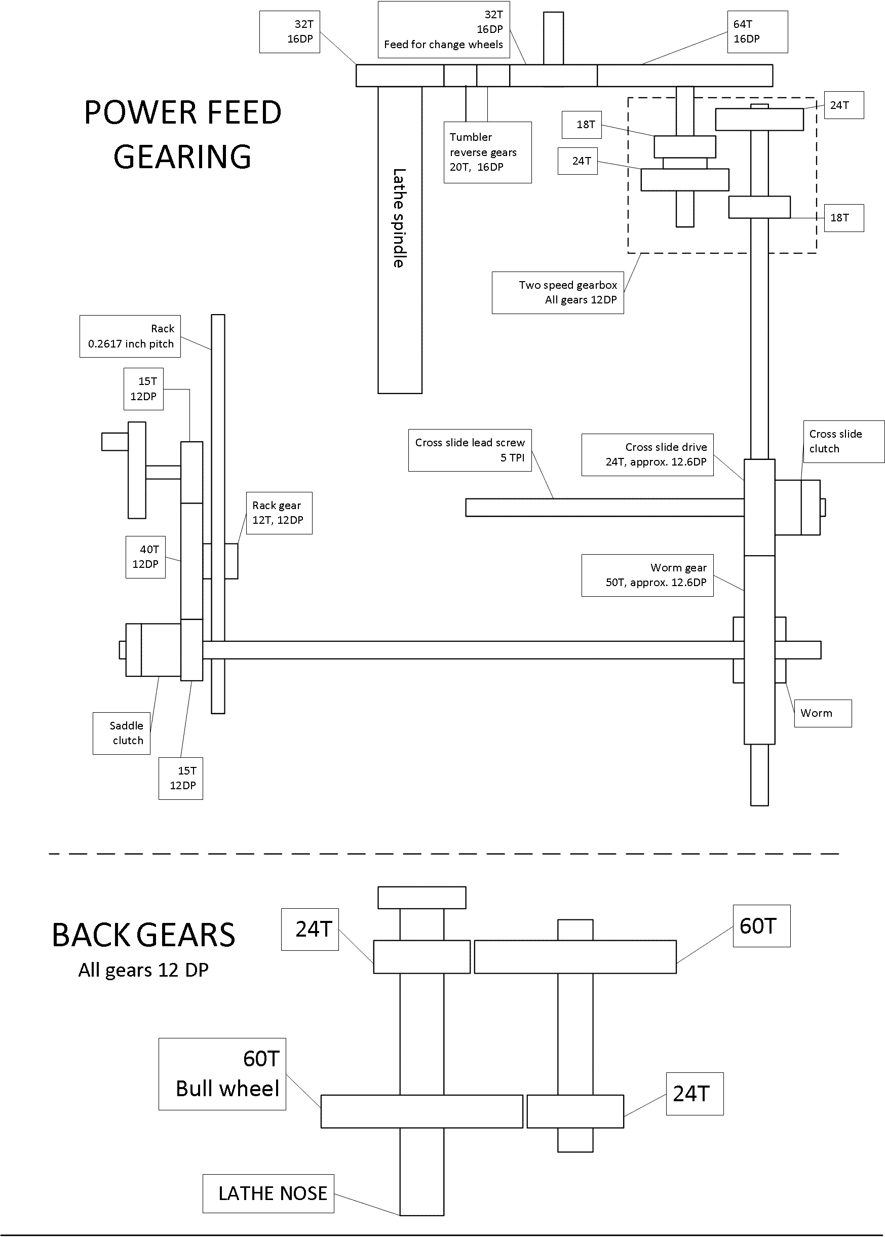
A diagram of all the gearing on the lathe but not including the changewheels
Inside of the two speed gearbox for the power feed. The gear ratios are 18:24 and 24:18.
External view of the power feed gear box. The 64T input gear is on the left and the drive shaft to the right. The spline that drives the worm gear is only on the end of the shaft so will not show in this picture.
The power feed gear box mounted on the lathe base. The 64T input gear is not fitted.
The power feed worm and worm gear. The gear and clutch for the cross-slide feed is at the top of the picture behind the worm gear.
The cross slide power feed provides a travel of 0.0056 inches and 0.0031 inches in high and low ratio respectively
The shaft providing the power feed to the saddle. 15T drive gear at the bottom half of the picture with the cone clutch and clamp nut on the end of the shaft.
Rear view of the apron. Power feed shaft is not fitted.
Top view of the saddle with the power feed shaft fitted.
The saddle power feed provides a travel of 0.0157 inches and 0.0088 inches in high and low ratio respectively
Change wheel plate fitted on the front of the apron. This is from where the list of Birmel change wheels was produced, shown in the table in the change wheel section.
Back end of the mandrel showing tumbler gears.
Output shaft at left hand end of the lathe where the first change wheel is fitted. Note the small hole where the 3/32 inch driving pin is fitted.
Headstock front lower bearing showing the oiling wick.
Headstock rear lower bearing showing the oiling wick.
Front of mandrel resting in its bearing. Note the scoring on the shaft caused by the oiling wick.
Rear of mandrel showing the power take-off gear (LHS) and the first back gear (RHS). Note the similar scoring to the front.
The lathe was supplied as a bare unit but was complete with a set of change wheels, the swarf tray, a single phase motor, a layshaft with 4-speed pulley and Sturmey Archer clutch, and a box of miscellaneous bits.
The single phase motor may have been the original and all the insulation was completely unusable and so it was scrapped. The layshaft was a large structure and would need a lot of construction to make a satisfactory mounting. So the decision was taken to use a three-phase motor driven from an inverter with a single speed pulley. This gives a mandrel speed at 50Hz of 815 RPM and the lowest practical speed using the back gear of about 27 RPM.
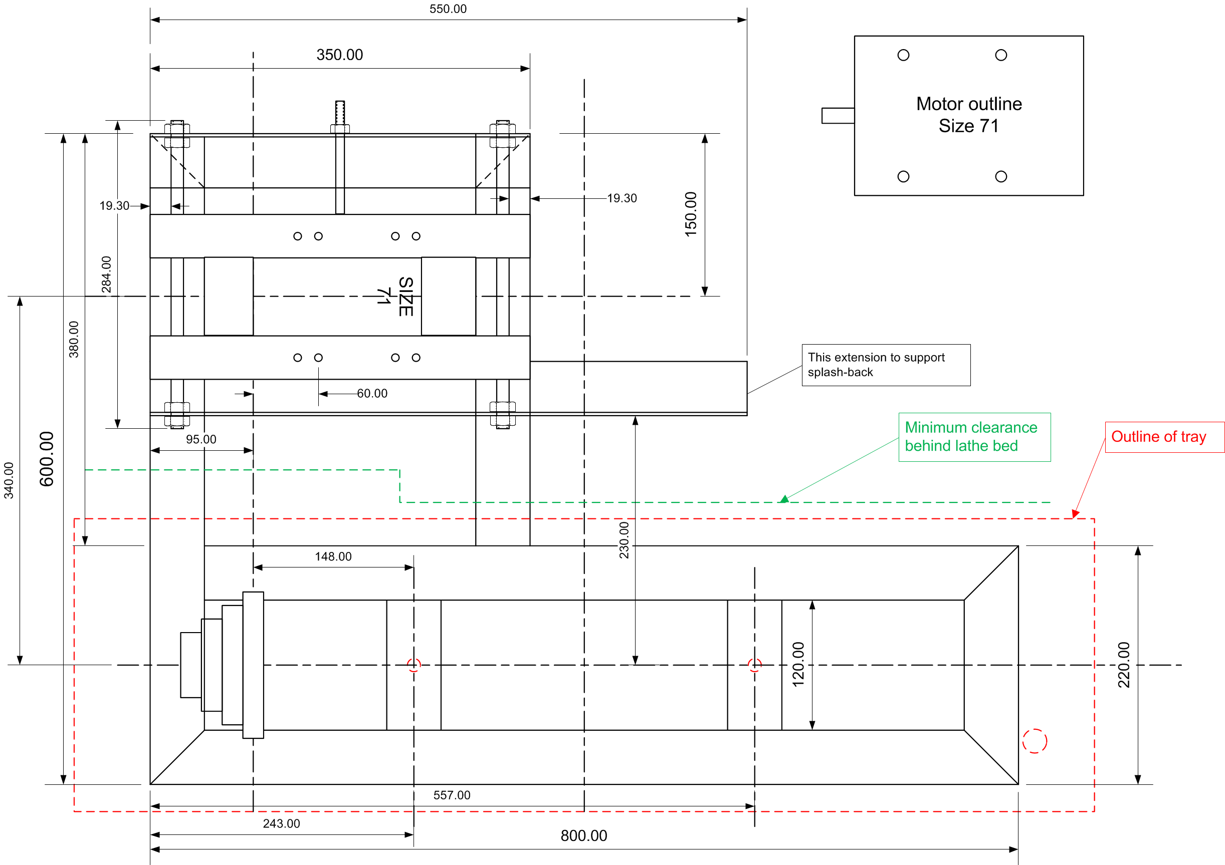
The previous lathe had been mounted on a simple wooden base with the motor on a simple Dexion frame - all very ramshackle. This lathe would have a rigid frame manufactured from steel box section 50 x 50mm box section 3mm thick.
The pictures show some of the manufacturing of the base.

A plan view of the base design. The main structure uses 50mm box section with L-section being used for the motor support and motor mounting plate.

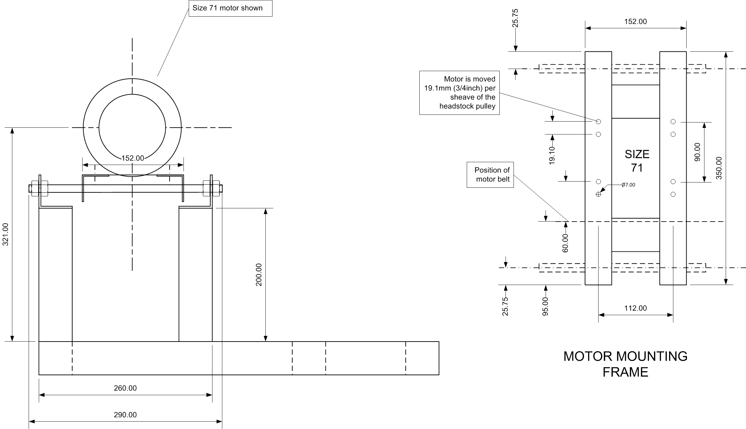
Side view detail of the motor mounting on slides.
Cutting the metal sections.
Drilling the holes for the motor slides in pairs.
All the metal ready for assembly.
Frame clamped to heavy metal section and first welds made.
Vertical sections for the motor mount clamped rigid for welding. Note the Argon bottle but an MMA welding holder on the bench; the frame was welded using a mixture of MMA and TIG.
Another view of the clamping for the uprights.
Detail of a TIG weld Note the less perfect MMA weld on the inside of the joint.
Cast iron elbow bronze welded to the underside of the swarf tray to provide a drain for cutting fluid.
Frame finished and painted.
Frame with swarf tray and raising blocks in place.
Detail of the motor mounting and sliding tension adjustment. At this stage the tensioning screws are not fitted.